Studio 3
By Thom Johansen (thomj@notam.no) and Niklas Adam (na@notam.no) • 15 minutes read •

Overview of Notam's studio 3
This document contains an overview of the setup and use of Notam's studio 3 (studio for spatial audio). It is composed of two parts, with the first detailing the hardware and the second containing a quick first use setup guide.
Technical overview
The loudspeaker setup is a slightly irregular hemisphere consisting of 24 loudspeakers in three rings. The lower ring of 12 speakers is placed in the horizontal plane at head height. The two additional rings placed further up consists of 8 and 4 loudspeakers respectively. In addition there is currently one subwoofer. The measured loudspeaker positions can be found in various formats in the ###Coordinates section. It is highly recommended that you utilize these if your software supports it because of the irregular distances to the top four speakers.
The loudspeaker type is KEF LS-50. The subwoofer (Genelec 7070A) is intended to provide the majority of the low frequency content, so the bass has been rolled off somewhat in the loudspeakers.
The sweet spot in the middle of these loudspeakers is at head height above the markings on the floor.
Controls
The controls you'll find on the desk are quite simple:
There is a mute/panic switch on the metal box. The 24 loudspeakers are together capable of excessive sound levels, so keep this switch close if there is a possibility of loud mistakes being made. This switch will disable all the loudspeakers (except the subwoofer) in all positions but the topmost/forward one. It's also a handy way of quickly muting all loudspeakers if you do something you know will generate a loud glitch, for example switching the sample rate. Please make liberal use of this switch, the amplifier is powerful enough to damage the speakers if you are supplying a loud enough signal. Please mute all speakers whenever you leave the studio. The mute switch currently does not mute the subwoofer, this is normal.
There is a volume controller in the shape of a white round knob. This controls the level of all loudspeakers, including the subwoofer. If you find that you need an even higher level than this can provide, ask the staff. Be advised that this indicates your material is at a rather low level.
Audio connectivity
On the table you will find an RME Madiface USB. This connects to your Windows or Mac computer via USB. When using this, your computer's output channels 1-24 will be sent to the loudspeakers (see diagram on last page for channel numbering). Output 25 is sent to the subwoofer.
The Madiface USB is supposed to be set up as clock master to allow you to select the sample rate yourself, but thanks to limitations in the hardware, the only easily supported sample rates are 44.1 kHz and 48 kHz. If you have a good reason for requiring either 88.2 kHz or 96 kHz, tell the staff. 192 kHz is not supported.
The audio connections in the studio are MADI based, which makes it non-trivial to connect other hardware to the system. We do however have solutions in place, so feel free to ask. As a quick summary, we can easily accomodate seven analogue line/mic inputs (via the patch panel in the front of the room) and MADI.
Gear list
Here follows the list of gear making up the signal chain in studio 3 for those who are curious.
RME Madiface USB. Used as an interface to the user's computer inside the studio. For more info, visit the RME Madiface USB details page.
RME Madiface XT. Connected to the Madiface USB inside the studio. Functions as a standalone volume controller and loudspeaker signal processor (bass management, etc.). More info here.
Ferrofish A32. Converts the MADI signal from the Madiface XT to analogue line signals. Also optionally converts any analogue signals from external equipment to digital MADI signals for use in the studio. More info here.
Sonible D:24. Amplifies the A32 line level signals and drives the 24 loudspeakers inside the studio. The subwoofer is currently active and needs no amplifier. More info here.
First time use
Setting up
Set the mute switch to one of the lower positions and the volume controller to a very low level (counter-clockwise).
Install the RME Madiface USB drivers at the RME download page.
- feel free to do this in advance if you are comfortable doing it. If in doubt ask the staff.
- Of the two available drivers for Apple computers, the Driverkit one is recommended. Once the driver is properly installed and you've rebooted, the Totalmix FX window should pop up.
- Some caveats involved with the driver install and Totalmix:
- If Totalmix shows up with a dialog window saying "detected", featuring "yes" and "no" buttons, press "yes" until it goes away.
- If you are using MacOS 10 (10.13 High Sierra or higher), read the special notice contained in the driver package for this operating system, or the driver will possibly not work.
How to choose the right RME Driver for your Mac Operating System
In the File menu of Totalmix, press "Load Workspace" and load the totalmix workspace file located here. Click "yes" if it asks you whether to discard all changes.
After switching the mute switch to the top position you should now be good to go, and all the loudspeakers in the studio will be available from your software of choice.
If you have any questions about the Madiface USB setup, please check the troubleshooting section.
- Notam's decoder files for usage with the IEM SimpleDecoder can be found here
Reaper template
Here you will find a Reaper template for ambisonics work with the IEM Plug-in Suite.
Troubleshooting
If you have any problems, first bring up the Fireface USB settings dialog window (should be found in your dock/task bar/system tray), and make sure the following options are set correctly (top to bottom):
- Output format set to "64 (32) ch." and "96K Frame"
- Sample rate is set to either 44100 Hz or 48000 Hz
- Clock source is set to "internal"
Totalmix should be set up properly after loading the workspace file provided, but as a quick summary, all output channels from 1 to 25 should be set to 0 dB, and channel routing from software to hardware outputs should be 1:1, as it is after performing a "Straight playback" mix reset in the options menu.
If the volume controller or mute switch does not work, please contact the staff.
When troubleshooting, please remember to set the studio volume knob at a low level and mute all speakers with the mute switch whenever you are doing something drastic like restarting equipment or connecting cables. There might be no sound when you are troubleshooting, but when you find the problem or manage to properly insert that last cable you forgot, you might be surprised at how loud you were really playing...
Speaker placement and channel order drawing
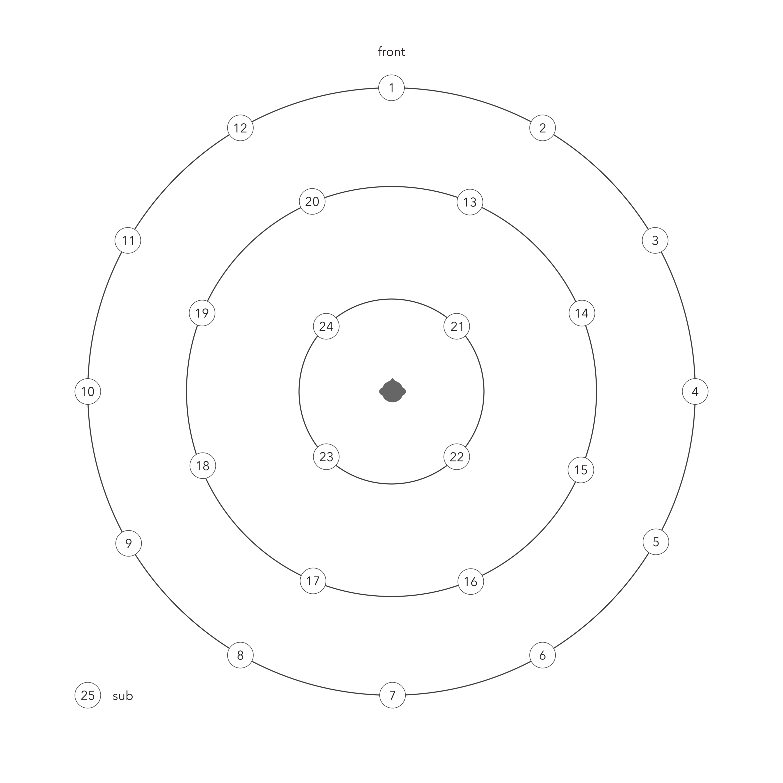 Figure 2.
Coordinates
Loudspeaker coordinates as of 29.11.2024
AED format:
- Angle, Elevation, Distance
- IRCAM Spat Compatible
- Positive azimuths CLOCKWISE
- 0 degree azimuth is forwards (front speaker)
0 0 2
30 0 2
60 0 2
90 0 2
120 0 2
150 0 2
180 0 2
-150 0 2
-120 0 2
-90 0 2
-60 0 2
-30 0 2
22.5 29.2 1.95
67.5 28.7 1.936
112.5 28.8 1.938
157.5 28 1.918
-157.5 28.8 1.931
-112.5 29 1.937
-67.5 28.8 1.939
-22.5 28.5 1.939
45 61.6 1.523
135 59.8 1.538
-135 60 1.545
-45 59.8 1.538
json AERC format
- Azimuth, Elevation, Radius, Channel
- Negative azimuths is CLOCKWISE
- 0 degree azimuth is forwards (front speaker)
Created via jq on Notam's decoder file found here
jq '.LoudspeakerLayout.Loudspeakers \
| sort_by(.Channel) \
| map(del(.IsImaginary, .Gain))' \
s3_iem_decoder_config_2024.json
[
  {
    "Azimuth": 0.0,
    "Elevation": 0.0,
    "Radius": 2.0,
    "Channel": 1
  },
  {
    "Azimuth": -30.0,
    "Elevation": 0.0,
    "Radius": 2.0,
    "Channel": 2
  },
  {
    "Azimuth": -60.0,
    "Elevation": 0.0,
    "Radius": 2.0,
    "Channel": 3
  },
  {
    "Azimuth": -90.0,
    "Elevation": 0.0,
    "Radius": 2.0,
    "Channel": 4
  },
  {
    "Azimuth": -120.0,
    "Elevation": 0.0,
    "Radius": 2.0,
    "Channel": 5
  },
  {
    "Azimuth": -150.0,
    "Elevation": 0.0,
    "Radius": 2.0,
    "Channel": 6
  },
  {
    "Azimuth": -180.0,
    "Elevation": 0.0,
    "Radius": 2.0,
    "Channel": 7
  },
  {
    "Azimuth": 150.0,
    "Elevation": 0.0,
    "Radius": 2.0,
    "Channel": 8
  },
  {
    "Azimuth": 120.0,
    "Elevation": 0.0,
    "Radius": 2.0,
    "Channel": 9
  },
  {
    "Azimuth": 90.0,
    "Elevation": 0.0,
    "Radius": 2.0,
    "Channel": 10
  },
  {
    "Azimuth": 60.0,
    "Elevation": 0.0,
    "Radius": 2.0,
    "Channel": 11
  },
  {
    "Azimuth": 30.0,
    "Elevation": 0.0,
    "Radius": 2.0,
    "Channel": 12
  },
  {
    "Azimuth": -22.5,
    "Elevation": 29.20000076293945,
    "Radius": 1.950000047683716,
    "Channel": 13
  },
  {
    "Azimuth": -67.5,
    "Elevation": 28.70000076293945,
    "Radius": 1.935999989509583,
    "Channel": 14
  },
  {
    "Azimuth": -112.5,
    "Elevation": 28.79999923706055,
    "Radius": 1.937999963760376,
    "Channel": 15
  },
  {
    "Azimuth": -157.5,
    "Elevation": 28.0,
    "Radius": 1.917999982833862,
    "Channel": 16
  },
  {
    "Azimuth": 157.5,
    "Elevation": 28.79999923706055,
    "Radius": 1.930999994277954,
    "Channel": 17
  },
  {
    "Azimuth": 112.5,
    "Elevation": 29.0,
    "Radius": 1.937000036239624,
    "Channel": 18
  },
  {
    "Azimuth": 67.5,
    "Elevation": 28.79999923706055,
    "Radius": 1.939000010490417,
    "Channel": 19
  },
  {
    "Azimuth": 22.5,
    "Elevation": 28.5,
    "Radius": 1.939000010490417,
    "Channel": 20
  },
  {
    "Azimuth": -45.0,
    "Elevation": 61.20000076293945,
    "Radius": 1.523000001907349,
    "Channel": 21
  },
  {
    "Azimuth": -135.0,
    "Elevation": 59.79999923706055,
    "Radius": 1.537999987602234,
    "Channel": 22
  },
  {
    "Azimuth": 135.0,
    "Elevation": 60.0,
    "Radius": 1.544999957084656,
    "Channel": 23
  },
  {
    "Azimuth": 45.0,
    "Elevation": 59.79999923706055,
    "Radius": 1.537999987602234,
    "Channel": 24
  }
]
Decoder
IEM AllRAD
Notam's decoders made with the AllRAD approach for usage with the SimpleDecoder:
If in doubt use the maxrE one.
For more information on the approach check IEM's AllRADecoder Guide
Use the same json file with the DistanceCompensator. Dont forget to enable the 25th channel for the sub. And same with the SimpleDecoder. Set the sub channel to discrete and choose channel 25.
Weights
These are two different decoder optimization strategies (also called "shelf filters" or "weighting schemes") used when decoding Ambisonics to loudspeaker arrays. They address a fundamental trade-off between spatial accuracy and perceptual quality.
A basic ("sampling") Ambisonics decoder reconstructs the sound field accurately in theory, but our ears don't perceive it that way in practice. Higher-order components contribute energy that can cause tonal coloration, diffuse imaging, or even unstable/phasey perception — especially with limited loudspeaker arrays. Weightings are applied to the Ambisonic orders to compensate.
MaxRE (Maximum Energy Vector)
MaxRE maximizes the energy vector (rE), which is a measure of the direction from which the listener perceives the majority of sound energy. It's derived from psychoacoustics — specifically, the idea that at high frequencies, the auditory system localizes based on energy rather than pressure.
- Applies a cosine-based window across orders: weights are
cos(π·n / 2(N+1))for order n in an order-N system - Tends to narrow the perceived source width and improve localization sharpness
- At the cost of a slight reduction in the accuracy of the reconstructed wave field
- Particularly important for high frequencies (above ~700 Hz), where the energy vector dominates perception
- Gives a longer rE vector — meaning perceived sound is more directionally focused
Think of it as: optimized for where the sound seems to come from.
InPhase
InPhase ensures that all loudspeakers in the array reproduce signals that are in phase with each other for a source at any direction. This prevents cancellation artifacts and phase conflicts between speakers.
- Applies heavier attenuation to higher orders than MaxRE
- Produces a wider, more diffuse image, but with robust, stable mono-compatible output
- Avoids negative loudspeaker contributions (no speaker ever "pulls" the image in the wrong direction)
- Important for low frequencies and for systems where listener position varies (e.g., large audiences)
Think of it as: optimized for stability and cohesion of the sound image.
Side-by-Side Comparison
| Property | Basic (no weighting) | MaxRE | InPhase |
|---|---|---|---|
| Goal | Accurate wave field | Max energy vector | All speakers in phase |
| High-freq localization | Poor | Best | Moderate |
| Image stability | Unstable | Good | Best |
| Source width | Narrow but phasey | Moderate | Widest |
| Order attenuation | None | Moderate | Heaviest |
| Negative speaker gains? | Yes | Sometimes | Never |
| Best for | Analysis | Playback (HF) | Large venues / LF |
Usage
In practice, a well-designed Ambisonics decoder uses both, applied in different frequency bands via shelf filters:
- Low frequencies (~below 700 Hz): InPhase weighting (or basic), because phase coherence matters more perceptually
- High frequencies (~above 700 Hz): MaxRE weighting, because energy-based localization dominates
This is the basis of the dual-band or "psychoacoustic" decoder described by Gerzon and later formalized in tools like the AllRAD and EPAD decoder designs.
Order Overview (0th – 7th)
In 3D (full-sphere) Ambisonics, each order N adds (2N+1) new spherical harmonic components. The total number of channels for a complete N th-order system is (N+1)².
Order Table
| Order (N) | New Components (2N+1) | Total Channels (N+1)² | ACN Channel Indices | Common Label | Spatial Detail |
|---|---|---|---|---|---|
| 0 | 1 | 1 | 0 | W | Omnidirectional — no directional information |
| 1 | 3 | 4 | 1–3 | Y, Z, X | Front/back, up/down, left/right — basic directionality |
| 2 | 5 | 9 | 4–8 | V, T, R, S, U | Quadrupole patterns — moderate spatial detail |
| 3 | 7 | 16 | 9–15 | Q, O, M, K, L, N, P | Octupole patterns — good localization, typical VR/spatial audio target |
| 4 | 9 | 25 | 16–24 | — | Fine directional resolution — high-quality immersive audio |
| 5 | 11 | 36 | 25–35 | — | Very fine resolution — approaching perceptual limits for most listeners |
| 6 | 13 | 49 | 36–48 | — | Extremely fine resolution — research / high-end reproduction systems |
| 7 | 15 | 64 | 49–63 | — | Near-theoretical maximum perceptual resolution for human hearing |
Channel Labels (FuMa Notation)
The letters come from FuMa (Furse-Malham) notation, the older naming convention for Ambisonic channels. Each letter maps to a specific spherical harmonic shape — essentially a 3D pattern describing which directions that component is sensitive to.
Order 0
| Label | Description |
|---|---|
| W | The omnidirectional component. Picks up sound equally from all directions — like a perfect omni microphone. It's the "base" of the entire sound field. |
Order 1
| Label | Axis | Description |
|---|---|---|
| X | Front/Back | Figure-of-eight pattern pointing forward and backward |
| Y | Left/Right | Figure-of-eight pattern pointing left and right |
| Z | Up/Down | Figure-of-eight pattern pointing up and down |
These three together with W give you a complete first-order B-format signal — the classic output of a Soundfield microphone, and the foundation of all Ambisonics.
Order 2
| Label | Description |
|---|---|
| R | Vertical "axial" component — a zonal harmonic aligned to the Z axis |
| S | Diagonal pattern in the XZ plane |
| T | Diagonal pattern in the YZ plane |
| U | Horizontal "saddle" pattern — differentiates front/back from left/right in the XY plane |
| V | Diagonal pattern in the XY plane, rotated 45° from U |
Order 3
| Label | Description |
|---|---|
| K | Zonal harmonic along Z axis (vertical, narrow lobe) |
| L | Tesseral pattern in the XZ plane |
| M | Tesseral pattern in the YZ plane |
| N | Sectoral pattern mixing X and Y axes |
| O | Sectoral pattern mixing X and Y axes, rotated |
| P | Diagonal pattern in the XZ plane |
| Q | Diagonal pattern in the YZ plane |
Useful intuition
The letters themselves are somewhat arbitrary — they're just shorthand tags assigned by Furse and Malham in the 1990s. What actually matters is the spherical harmonic function each one represents, which determines its polar pattern in 3D space.
A useful intuition is that as you go up in order:
- Order 0 — one blob, no directionality
- Order 1 — adds three figure-of-eight lobes along the three axes
- Order 2 — adds five more complex "clover-leaf" and saddle shapes
- Order 3 — adds seven even more intricate patterns
Each new set of patterns fills in finer and finer angular detail, which is why higher orders give better spatial resolution.
Modern systems (AmbiX / ACN+SN3D) dropped the letter names entirely above order 1 and just use the numeric (N, M) degree/order index, which scales cleanly to any order without needing to invent new letters.
Notes
- ACN (Ambisonic Channel Numbering) is the standard modern ordering, defined as
N² + N + Mfor degree N, order M. - Channel count grows quadratically — doubling the order more than quadruples the channels.
- 3rd order (16ch) is the most common target for practical spatial audio (e.g. game engines, VR headsets, streaming).
- HOA (Higher Order Ambisonics) typically refers to order 2 and above.
- Component letter names (W, X, Y, Z, etc.) are used in FuMa notation and only standardized up to order 3; higher orders are typically referred to by their ACN index or (N, M) degree/order pair.
- The SN3D normalization scheme (used in AmbiX format) is the current standard for encoding these components.
Recommendations
Many workflows are possible in our Spatial Audio Studio.
The staff is mostly using Reaper with the IEM Plug-in Suite and SuperCollider with ATK.In general we work with Ambisonics and VBAP. But if needed Dolby Atmos is possible. ^^.